large cars
Driving school
theory book
for category C - D - C/E - D/E
Large cars and lorries
Large cars - Categories C and D.
3. Brakes
Cars are equipped with brakes in order to stop the vehicle safely, quickly and efficiently. The brakes are thus a very important element of safety, and it is therefore important that you have sufficient knowledge of the brake system, its operation and maintenance to ensure that the brakes are working properly and that any faults are detected in time.
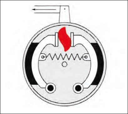
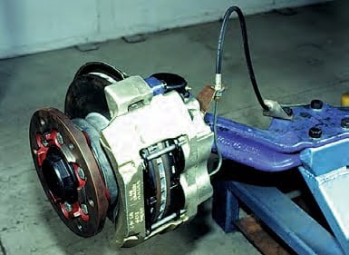
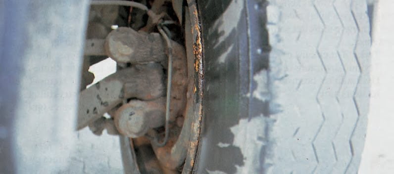
Wheel brake consists of a stationary part that carries brake shoes or brake pads, and a rotating part, which can be either a brake drum or a brake disc.
Drum brake basically consists of a set of brake shoes that can be mechanically or hydraulically pressed against the brake drum.
Mechanical wheel brake with >>S<< key
A wedge or brake key is placed between the brake shoes, which presses the brake shoes against the brake drum when braking.
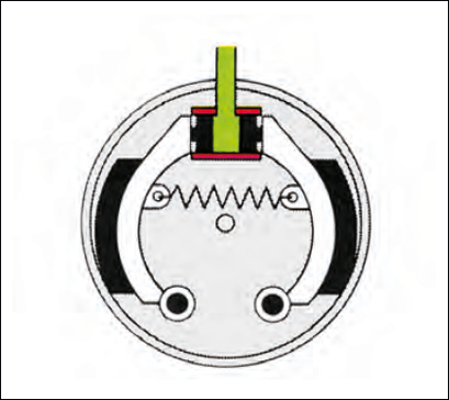
Hydraulic wheel brake
When braking, the amount of fluid in the wheel cylinder increases and pistons press the brake shoes against the brake drum.
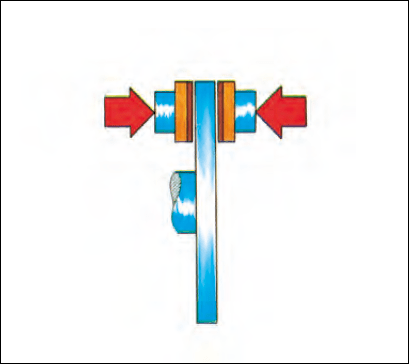
Disc brake
The disc brake is a set of brake pads that are pressed against the brake disc using hydraulics or compressed air.
The brake drum or disc rotates together with the wheel. When braking, the brake shoes are pressed against the brake drum and the brake pads against the brake disc. The rotation of the wheel is now slowed down due to the frictional resistance between the rotating part and the stationary part.
The drum brakes can be adjusted and the distance between the brake shoes and the brake drum can be adjusted as the brake lining wears. The adjustment can optionally be automatic. Disc brakes are self-adjusting. Checking the wear of the brake pads is necessary to avoid damage to the brake disc (indicator light).
Signs of failure:
- Oil lubrication of the anchor plate or the inside of the tyre can be a sign of a leaking hydraulic wheel cylinder.
- Skewed braking or uneven braking indicates moisture or dirt on brake pads or defective wheel brakes, brake cylinders or brake diaphragms.
- Uneven braking or sudden chopping from one or more wheels indicates a faulty brake drum/brake disc or brake pad.
- Reduced braking performance indicates a lack of brake adjustment or an incorrectly set, possibly defective, ALB valve.
Compressed air brakes
Braking a heavy car or lorry requires more force than humans can manage.
To achieve sufficient power for braking, the car is equipped with compressed air brakes, which can be configured as one of the following systems:
- Compressed air mechanical brakes.
- Compressed air hydraulic brakes.
The compressed air system in a car is basically structured as follows:
A pump (compressor) pumps air into a container until a certain pressure (compressed air) is reached.
Compressed air braking occurs when you step on the brake pedal and press a valve that opens the compressed air. Through pipes, the compressed air is directed to a cylinder containing a piston (or diaphragm) that converts the pressure of the compressed air into a movement that activates the wheel brake.
This means that it is the 100% compressed air that affects the mechanical or hydraulic braking system and in the event of a lack of compressed air, the car will not be able to brake.
The compressed air system consists of the supply circuit, where the compressed air is created and stored, and the brake circuit, where the compressed air is converted into a force to apply the wheel brake.

The supply chain
The supply circuit that delivers compressed air to the brake circuit consists of the following parts:
Compressor, pressure regulator, frost protection pump (possibly air dryer), pressure relief valve, compressed air tank, alarm device, pipes and hoses.

Compressor
The compressor is a pump that sucks air from the outside through a filter and sends it to the supply circuit as compressed air. The compressor is powered by the car's engine.


The compressor must be able to fill empty compressed air cylinders in less than 3 minutes until the control light switches off or the alarm goes off. I.e. when 2/3 (65%) of the working pressure has been reached.
Signs of failure:
- If the inflation time is too long, it could be a sign of a worn compressor, clogged air filter, leaks in the brake system.
- A shorter inflation time than usual or a high pressure drop at full braking can be a sign of water in the compressed air cylinders.

Pressure regulator
The pressure regulator keeps the pressure in the supply circuit within the prescribed limits by automatically switching the compressor on and off. When the highest working pressure
(cut-off pressure) is reached, the pressure regulator overrides and the compressor is relieved by venting the air to the outside or by sending pressure (an impulse) to the compressor and lifting its intake valve. When the pressure in the supply circuit has dropped to the lowest working pressure (cut-in pressure), the pressure regulator reverses and the air from the compressor is directed to the supply circuit.

The pressure regulator is checked as follows:
The pressure gauge reads whether the pressure in the supply circuit is kept within the compressed air limits mentioned in the car's instruction manual (the limits may also be marked on the pressure gauge).


Frost protection pump
Adding antifreeze prevents malfunctions due to ice formation in the compressed air system. When the temperature is +5°C and below, it is necessary to secure the system. The frost protection pump can be automatic or manual. The manual frost protection pump is operated according to the instructions in the manual.
You have to control:
The fluid level should be between the minimum and maximum mark on the fluid container or dipstick.

Air dryer
A much better way to protect your compressed air system from freezing is to use an air dryer. The air coming from the compressor flows through
a special filter where the humidity is collected.

In a special subsequent process, the filter is cleaned of the collected water. An additional advantage of the air dryer is that there is no condensation, which can damage the valves in the brake system.
Inspection and maintenance
Change the filter according to the instructions in the manual.
You have to control:
When the air dryer is operating, there must be no condensation in the compressed air tanks.


Pressure safety valve (multi-circuit safety valve)
The pressure relief valve acts as a distribution and safety valve. The valve distributes the compressed air from the compressor to all circuits in the supply system.
If a circuit becomes leaky, the valve must ensure 2/3 (65%) of the working pressure in the other circuits. The valve can be checked by emptying the circuits individually of compressed air.


Compressed air tanks
Compressed air tanks store the compressed air and must be able to be drained of condensation, possibly automatically. On vehicles with air dryers, the drain option may be omitted.
Checking compressed air tanks:
Check that the compressed air tanks are securely fastened and not visibly corroded. They must be able to be emptied of condensation without the use of tools, this should be done daily in winter and every 5,000 kilometres in summer.

Signs of failure:
Water in the container can be a sign of an inoperative air dryer.


Alarm device
The alarm device, which is a lamp or buzzer, is intended to alert the driver that the air pressure in the supply circuit is too low. The alarm device can be replaced or supplemented with a pressure gauge that shows the pressure in the supply circuit and possibly also in the brake circuit.

Checking the alarm device
Check that the lamps or buzzer switch on when the pressure in the supply circuit is below 2/3 (65%) of the working pressure and switch off when the pressure is above this limit.
Warning signal
Newer trucks may be equipped with a display that warns of faults in the braking system.
Pipes and hoses
Pipes and hoses connect the individual parts of the supply circuit.
Signs of failure:
Pipes and hoses must be tight and free from corrosion, cracks or leaks.
Brake circuit (compressed air mechanical brakes)

The brake circuit is the part of the braking system that is pressurised when the brake pedal is applied, thereby activating the wheel brakes.
The brake circuit consists of the following main parts:
- Brake pedal/brake valve.
- Brake force regulator. (ALB valve).
- Brake diaphragms.
- Pipes and hoses.
- Wheel brakes.
If the braking system is designed as ABS, in some cases there will be no brake controller. If ABS does not work, it is illegal to continue driving.
Brake pedal
When operating the brake pedal (and thus the brake valve), compressed air is directed from the supply circuit to the brake circuit. The further the pedal is depressed, the greater the pressure in the brake circuit. If there is no compressed air, the brakes will be ineffective.

The brake valve is checked as follows:
Must have less clearance in the top position. The brake pedal must be able to be depressed to a fixed stop so that the brake valve opens fully.
Brake force regulation (ALB valve)

1. ALB valve.
2. Vibration damper.

The brake force regulator (ALB regulator) automatically adjusts the braking force to the car's load. The ALB controller is usually mounted on the chassis frame and is mechanically connected to the wheel axle.
Checking the ALB controller:
The ALB regulator's mechanical connections must be intact and the valve arm must move freely. Check the function of the regulator with the service brake engaged and by moving the valve arm up and down. This should change the air pressure in the brake circuit, which may be heard as air leaks from the brake circuit. However, this check cannot be performed on all types.
ALB with air suspension
On cars with air suspension, where the distance between the chassis frame and the axle is the same regardless of the load, the brake force regulator is controlled by the pressure in the air bellows. The air pressure in the air bellows increases with higher loads. When the bellows pressure changes, the control pressure at the air-controlled ALB valve, which regulates the compressed air to the brake diaphragms, also changes.
Signs of failure:
Reduced braking performance indicates, among other things, an incorrectly set or defective ALB valve. Rear wheel lock during moderate braking may indicate an incorrectly set or defective ALB valve.


Air-operated ALB valve


Brake diaphragms
Brake diaphragms, located near the wheels, are tasked with converting the energy of compressed air into movement and force to apply the wheel brake.
The piston travel of the brake diaphragm must not exceed one quarter of the diaphragm housing clamping band diameter.
Brake adjustment
As the brake lining wears, the stroke increases. Braking performance decreases or fails completely when the stroke length becomes too long. Brakes then need to be adjusted, which happens
by adjusting the brake spanner lever. Newer cars (1996) have automatic brake adjustment. It is important that function and stroke length are checked and adjusted regularly. With heavy braking, the check should be done frequently.

Self-adjusting brakes
Self-adjusting brakes are often equipped with an indicator ("tell-tale device") that indicates the amount of remaining brake lining. With the "indicator arrow" standing as the mark (1), the full amount of brake lining. When the "indicator arrow" (1) is horizontal upwards and next to the mark (2), it indicates worn brake lining.

Signs of failure:
Extended operating time or excessive consumption of compressed air and thus high pressure drop during braking can be a sign of excessive piston travel in compressed air diaphragms or cylinders. Excessive pressure drop can also be caused by water in the compressed air tanks. During full braking (with the brake pedal fully depressed), the pressure drop should generally not exceed 0.5 bar.

Pipes and hoses
Pipes and hoses connect the individual parts of the brake circuit.
Signs of failure:
Pipes and hoses must be tight and free from corrosion, cracks or leaks.
Leak test/load test
Checking the tightness and load of compressed air-mechanical and compressed air-hydraulic brakes is fulfilled in both the supply circuit and the brake circuit, as judged by the following test:
Perform a leak test by pressurising the supply circuit to the lowest working pressure. With the brake pedal in the down position, start the engine and pressurise to the highest working pressure, stop the engine, keep the brake pedal depressed and listen for leaks.
If this can be done without a sudden drop in pressure (read on any pressure gauge) and without audible leaks after stopping the engine, the system can withstand sufficient load.
Working pressure:
The system must have the necessary working pressure (according to the vehicle manufacturer's instructions) before driving.
Compressed air hydraulic brake

Transformers
The air-hydraulic brake system consists of a compressed air part (supply circuit and part of the brake circuit) and a hydraulic part. The brake pedal (and thus the brake valve) regulates the air pressure to a compressed air cylinder that acts on the piston of a hydraulic master cylinder. This converts the air pressure into hydraulic pressure.
The hydraulic pressure is channelled through pipes and hoses to the wheel brakes. The compressed air cylinder and the hydraulic master cylinder are connected together and are called the transformer. If there is a lack of compressed air or insufficient brake fluid, the brakes will be ineffective.
Compressed air hydraulic brakes are checked as follows:
The brake pedal must be able to be depressed to a firm stop to fully open the brake valve. Must have a smaller clearance in the top position.
Pipes and hoses must be tightly clamped and free from corrosion, cracks or leaks, judging by immediately accessible parts. Mechanical brake force regulator (ALB valve)
must have an intact mechanical connection. Depending on the type, the valve arm must be able to move freely. As a general rule, the air consumption during full braking should not exceed 0.5 bar, as this may indicate a lack of brake adjustment, resulting in longer piston travel.

ALB valve (hydraulic)

1. Measuring stick
Brake position.
The piston travel of the converter must not exceed the limits specified in the instruction manual, as judged by the travel of the dipstick or by a control light. The master cylinder brake fluid reservoir must have a fluid level between the minimum and maximum marks of the reservoir. Too low a fluid level should illuminate the indicator light on the instrument panel.
Signs of failure:
Extended runtime or high compressed air consumption can be a sign of excessive piston travel in a transformer. Oil lubrication of the anchor plate or the inside of the tyre can be a sign of leakage in a hydraulic wheel cylinder.

Leak test/load test
The compressed air system must be sufficiently tight and must be able to withstand sufficient load in both the supply circuit and the brake circuit and be tested as with compressed air mechanical systems.
Combination of braking systems:
- The braking system can (most commonly on buses) be a combination of air-mechanical and air-hydraulic brakes.
Hydraulic brake with vacuum reinforcement
The service brake on lighter cars may be supplemented with a vacuum booster that amplifies the hydraulic pressure when the driver presses the brake pedal. Vacuum is supplied either from the petrol engine's intake manifold or from a pump (diesel engines). In the absence of vacuum, the car can be braked by the driver's pedal pressure alone, but braking will be weaker and continued driving will be dangerous and illegal.

ALB valve
The vacuum booster is checked as follows:
With the engine stopped, depress the brake pedal a few times to "remove" the vacuum from the booster. Then keep the brake pedal depressed while starting the engine. The pedal should now sink a little if it does not sink, there is a fault in the vacuum system.
Signs of failure:
Long pedal travel in a hydraulic system with reinforcement can be a sign of a lack of brake adjustment. A springy brake pedal in a hydraulic system with amplification can be a sign of air in the hydraulic system, among other things.
On smaller buses (max. 3500 kg) with hydraulic brakes, the service brake will in practice have such an effect that the braking distance at 30 km/h. at all load conditions does not exceed approx. 6 metres.

1. coasting 2. braking 3. Prohibited
Emergency brake - ABS system - Parking brake

1. Diaphragm cylinder 2. Sensor 3. control valve 4. brake valve 5. control unit (microcomputer)
Emergency brake
The purpose of the emergency brake is to be able to stop the car if the service brake fails. The emergency brake is either contained in the service brake or the parking brake.
Anti-lock brakes (ABS system)
Design and effect of anti-lock brakes (ABS brakes). All types of braking systems can be designed as ABS brakes. The ABS system is designed in such a way that sensors are installed at each wheel, which detect the rotation of the wheel by means of a ring gear. The sensors send signals about the rotation of the individual wheels to an electronic control box. If one or more wheels tend to lock during braking, the electronic control box will adjust the pressure to the wheel brakes to prevent the wheels from locking. The ABS braking system is designed in such a way that it enables steering and braking at the same time to a certain extent. When braking with a lorry with ABS brakes, the ABS braking system ensures that the wheels are kept in rotation and do not lock. When the ABS braking system regulates, some smaller trucks may experience vibrations in the brake pedal. This is normal and means that the system is working. Regardless of the vibrations, the pressure on the brake pedal must be maintained for as long as braking is desired. If the ABS braking system is not working, the braking behaviour will change and only driving to the nearest workshop is permitted.

Anti-blocking system (ABS)
The ABS system must have an indicator light that switches off when the speed reaches approx. 5 km/h. If the light does not go out or starts to light up while driving, the system is faulty and continued driving is illegal (only driving to the nearest workshop is permitted). All types of braking systems can be equipped with ABS.
Parking brake
The parking brake must be able to keep the car stopped on steeply sloping roads. (Legal requirement: 18% slope.) Mechanical parking brakes work by transmitting the driver's pull on the handbrake lever through rods or cables to the wheel brakes on one or more axles.

Spring brake (parking brake)
The spring brake is released by compressed air pushing a piston against a now compressed spring. When the parking brake lever is activated, the compressed air is removed and the force of the spring is now sufficient to brake the wheels on the axle.

The spring brake cylinder is usually built together with some of the diaphragm cylinders of the service brake, so that both brakes work through the same brake wrench arm.

Brake position
The spring brake is released using compressed air. The manual provides instructions on how to release the brake if the pressure in the air system is too low.

Free standing
Parking brake (spring brake) is activated using the handbrake valve

Handbrake valve
Functionality
The handbrake valve has three functions
- Emergency braking.
- Parking brake.
- Control mode.
(does not occur on all handbrake valves).

Mode of action
When the handle is turned the first distance, the emergency brake (car spring brake and trailer service brake) is activated. The braking force is steplessly adjusted according to the distance the handle is turned.
To check whether the car's parking brake alone can keep the vehicle combination braked if the trailer's compressed air disappears, turn the handle further to the check position (-the trailer braking stops and the vehicle combination is only braked using the car's spring brake).
Checking the parking brake:
When activating the spring brake to the braking position, you should hear the compressed air seeping out of the cylinder.
With other parking brake types, it must not be possible to pull the handbrake lever to the bottom position.
Additional brakes
To limit wear and heat generation at the wheel brake, an auxiliary brake can be used. The most commonly used auxiliary brakes are the engine brake and the retarder.
- The engine brake is an auxiliary brake, where a damper blocks the exhaust gas at the same time as the fuel supply is shut off, creating a (weak) braking effect on the drive wheels.

Engine brake
- The electric or hydraulic auxiliary brake (retarder) is usually built together with the propeller shaft and reduces the rotation of the propeller shaft, thereby
there is a braking effect on the drive wheels.

Electric auxiliary brake
- Reverse brake is a system that automatically brakes the car using the service or parking brake when the car is in reverse gear and a sensor at the rear of the car is touched.

1. Thermostat 2. Heat exchanger 3. Retarder 4. Gearbox 5. Engine 6. Cooling water pump 7. Radiator 8. Rotor 9. Stator 10. Oil flow
Other legal provisions on brakes
- The car must be equipped with a dual-circuit service brake, emergency brake and parking brake. Newer cars must be equipped with ABS brakes.
- The service brake must work on all wheels and be capable of slowing and stopping the truck safely, quickly and effectively at any speed and under all load conditions. The required effect of the service brake must be achieved by the first application of the brake pedal.
- On systems without a pressure gauge, the compressor must be able to fill empty compressed air tanks in less than 3 minutes until the control light switches off or the alarm is cancelled. On systems with a pressure gauge, 2/3 (65%) of the working pressure must be achieved in less than 3 minutes.
- The parking brake must be able to hold the car stationary on a 18% inclined road and must be able to remain applied.
- The emergency brake must be able to safely and effectively slow and stop the vehicle in the event of a service brake failure.
When driving on a horizontal, dry road with an asphalt surface, check that the following requirements are met:
The permitted braking distance at 30 km/h for trucks and buses is approximately 10 metres.
- When the brake pedal is depressed slowly, the braking effect must increase steadily (as judged by a practical brake test).
Schematically, the braking distances look like this:

1. the brake pedal is depressed 2. The distance the car is travelling during the function time 3. The distance used for braking